The carry mechanism
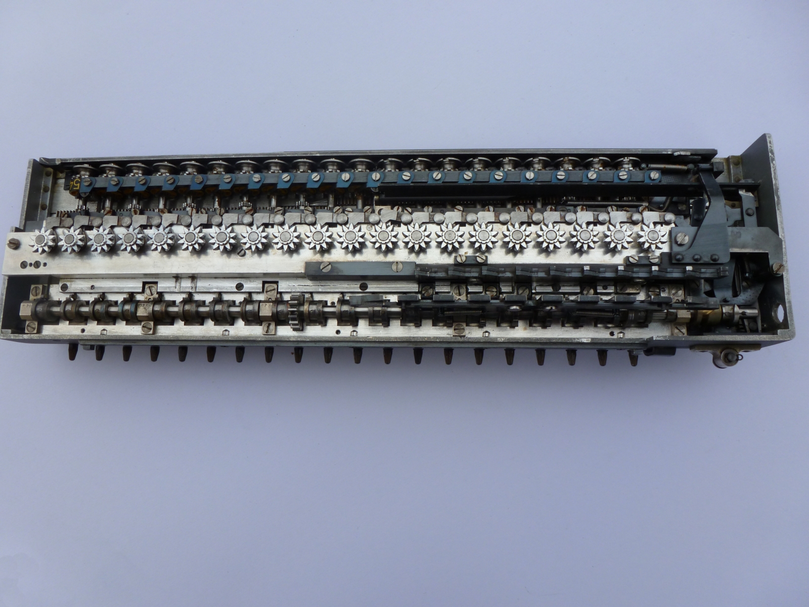
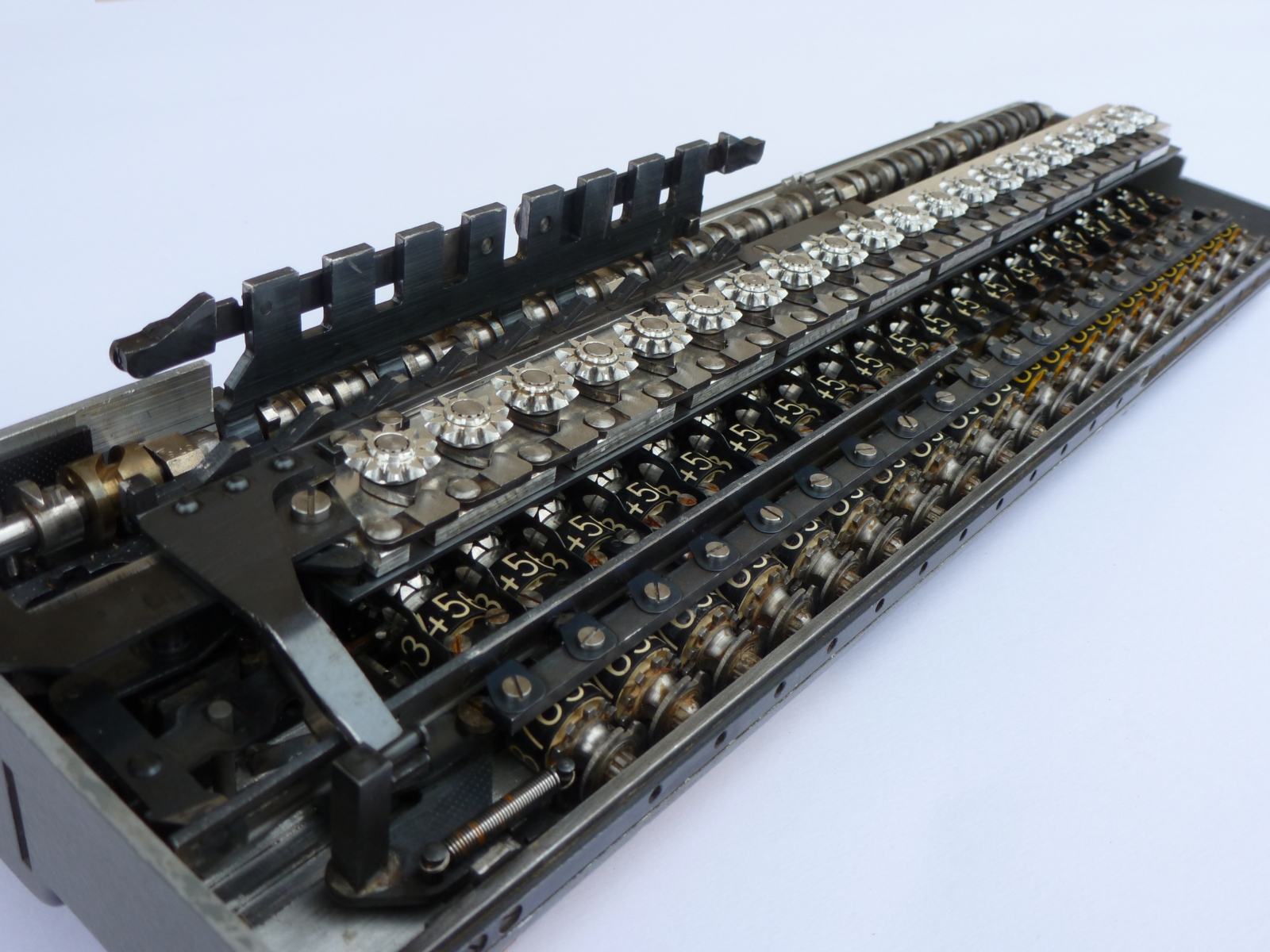
The first step is to observe the carriage underneath. The photos here below show the carriage of a 20BTG model. You can see the twenty cogwheels corresponding to the Product Register (Register I). In front of each cogwheel, there is a moving pawl which plays the lead in the carry mechanism (click on the photos for zooming). In close-up, we see that there is a finger attached to the cogwheel, which pushed forward the pawl, just while the corresponding counter digit goes from 9 to 0.
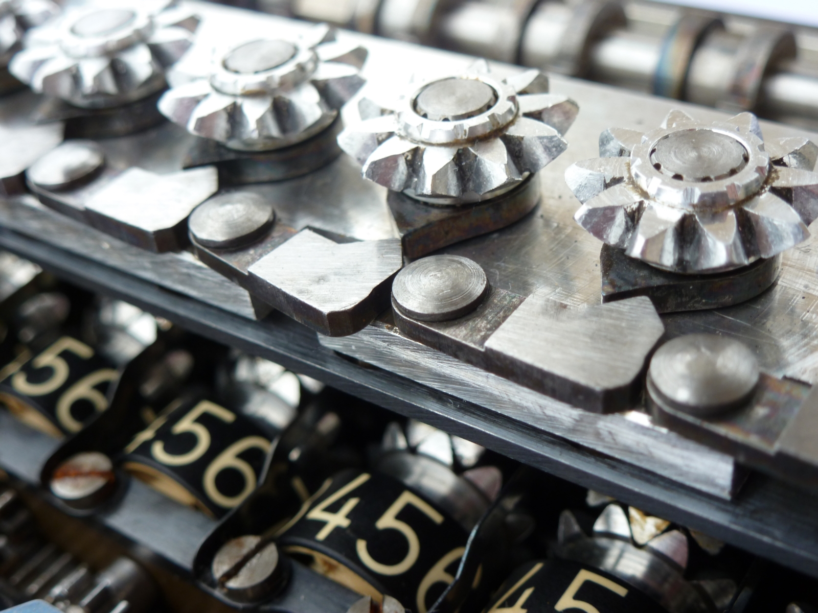
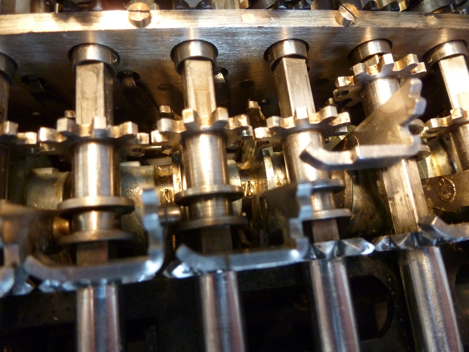
At left, we see that one pawl is pushed forward.
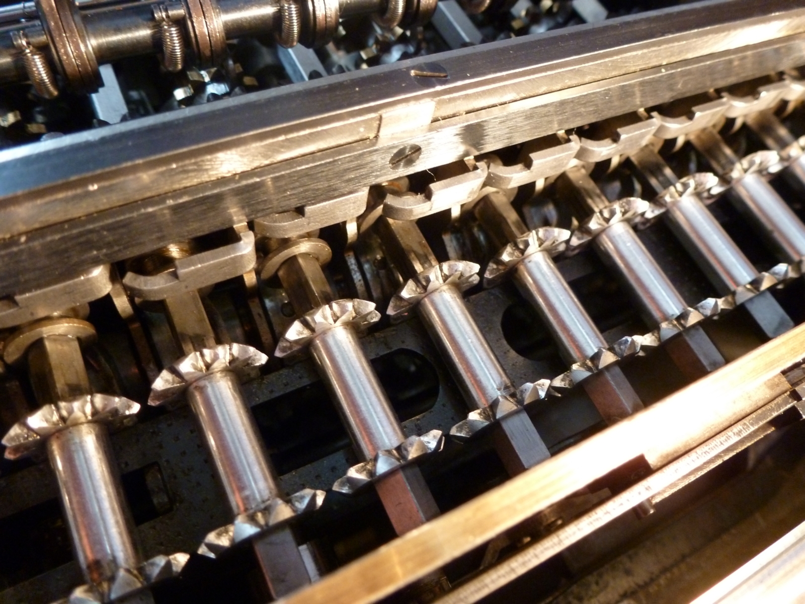
This pawl pushes itself forward a carry sense lever, situated just under a long brass bar, and above a camshaft which is fitted with one slotted cam for each digit.
The photos below show that the third carry sense lever is pushed forward, forcing the fourth carry pinion to be aligned with a finger which has to catch it and rotate it one step. We have removed the brass bar to have a better view of the sense levers and fingers.
From left to right, only the last pinion can be caught by the carry finger, which we see just underneath.
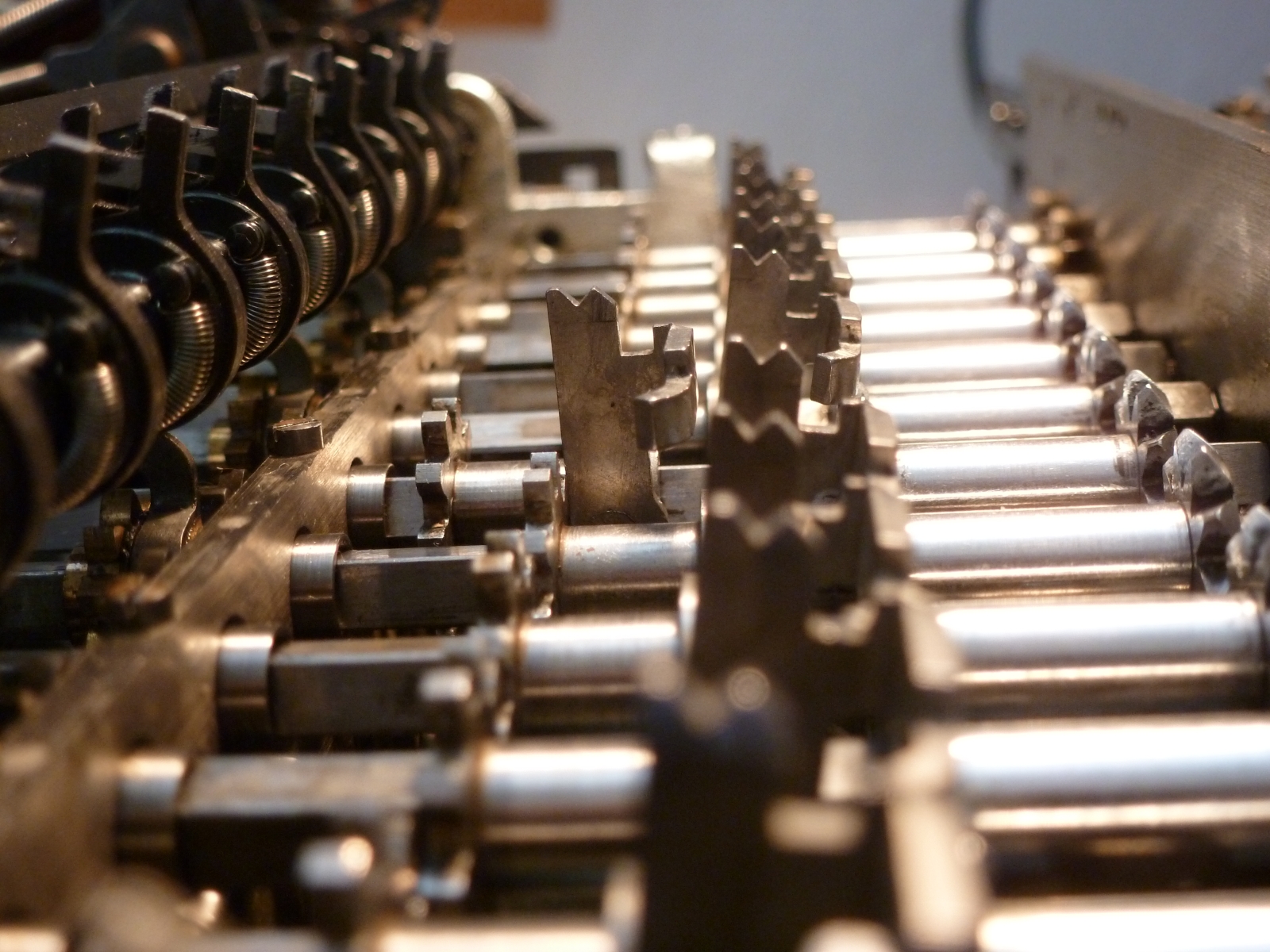
View from the right-hand side of the machine
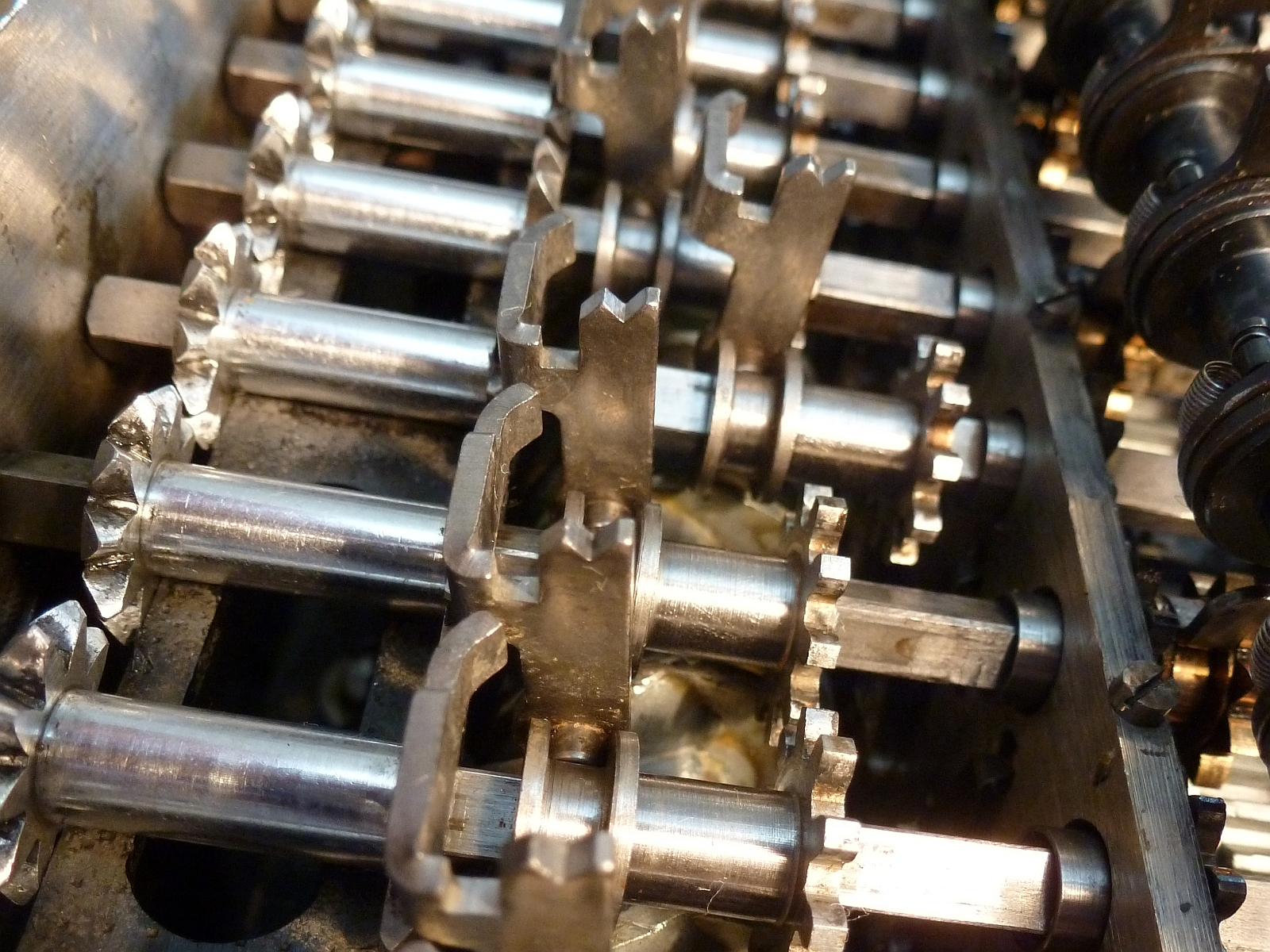
View from the left-hand side of the machine
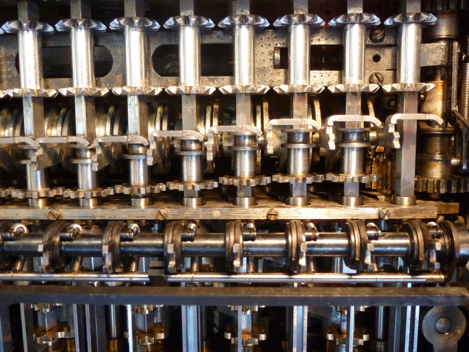
When the carry operation is completed for all digits, the slotted cams push the sense levers rearward to their original position. This process, beginning sequentially from the least significant digit, is made in an asynchronous way, as we can see here above, while each cam is not exactly aligned with regard to the one right nearby. As a matter of fact, it is this gap between the cams which allows propagating the carry on several tens.